Electronic Design
My assignment for week 6 was to redaw the Hello board and add an LED with and a Switch and test it if connection is optimal. After competing the redraw, I have to mill and stuff the board and see if it is working.
I decided to add 1 LED and a switch in my board.
Eagle
I downloaded Eagle software in week 4 through autodesk so using Eagle I added the Fab library from fabacademy.org .
Download the link through here fab.lbr
The Fab library is a all the components required for fablab week 6 project. When opening eagle press add then open the fab.lbr and dowload it.
After adding the Fab library in the Eagle I started adding the required components as shown in the hello board brought from the fab academy website as shown below:
Components Required to be redrawn:
•.ATtiny44-SSU
•.20mhz resonator
•.AVR ISP SMD header
•.FTDI SMD header
•.10K resistor
•.1µF capacitor
•.GND
•.VCC (5V)
plus adding 1 LED and a switch.
I started redrawing using the schematic board in Eagle and adding the required components from the library.
There are two type of connection in eagle using NET we can add the components manually and while LABEL we can add them automatically. Then I started connecting as given from the Hello board.
I organized the components inside the barriers then I started using autorouter automatically organize the connections and reach the optimal routing of 100%.
Finally with ripups and trial and error I achieved my optimal 100% connection routes as show in my pic below:
As adding the LEDs I also added for every LED one resister and the switch (button)
PCB Milling Machine
I converted my saved file through cam processor in Eagle and then go to job process to to convert it to cmp file "Gerber File"so that the file can be read in Cirqwizard for the milling machine “Cirqoid”. Hello Board File
I uploaded my schematic board in the Cirqwizard and then I go to n the control panel to test it first the right depth needed before cutting and the required x,y and z axis.> I used 0.2 mm to 0.25 mmm bit with a velocity 1390 micro second and then I gave it a test run and Once I reached the right dimension I started to the milling of my copper board.
Finalizing my copper board and preparing to solder the required components. I soldered the components together. I tested my board after soldering to check for any short circuit Soldering As in week 4, I took all the required components to organize it for soldering. The required components are for my board are as follow: My components: •.Ttiny44-SSU •.20mhz resonator •.AVR ISP SMD header •.FTDI SMD header •.10K resistor •.1µF capacitor •.GND •.VCC •.1 LEDs •.Switch •.1 resistors 120 K (ohm law vs-vf/I= 5-2.8/0.2 =/ approx 110 ohm) note: we don't have 110 ohm so I used 100 ohm.
.jpeg)
Problem
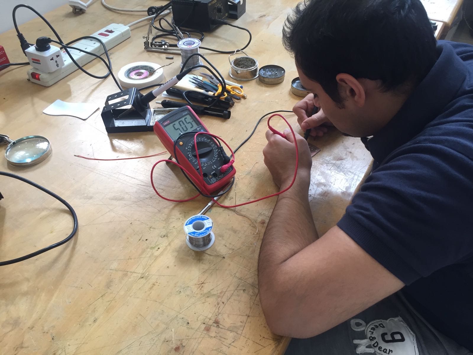
I made a mistake by increasing the heat of my iron plug (700 degrees) thus while soldering the ISP the route had been burnt inside the copper board and link have been broken.
The solution it resolve this issue and fix the route is by first try to use the lead and solder the route by it. By using the multimeter ( a tool used for measuring different electrical values), I have found that the route with the ISP still disconnected so as final measure I connected an electrical wire between the ISP and the route to form a new route.
The electrical wire I used for linking the ISP and the broken route.
The Result:
My hello board finally is done and ready to be programmed.